SolarSURFER — CubeSat (6U)
Design work focused on structure, deployables, and systems integration for a solar‑sailing CubeSat

SolarSURFER (Solar Sail Utilizing Radiative Forces Examining Radio‑waves) is a 6U CubeSat concept that investigates sail materials, reflectarray high‑gain antennas, and inflatable/rigidizable boom deployment to enable solar sailing from LEO. The project pairs sail propulsion experimentation with integrated communications and hyperspectral science instrumentation.
- Form factor: 6U (30 × 20 × 10 cm) with a ~15 × 15 m sail stowed in 4U.
- Primary goals: sail deployment and material testing, sail‑as‑HGA reflectarray, and power + instrument integration.
- Project artefacts: CAD assemblies, deployment mockups, reflectarray unit‑cell HFSS models, and test procedures.
Mission highlights (from technical documents)
The technical document details sail composition (ultra‑thin CP1/Kapton backbone with Al+Au coatings and targeted reflectarray regions), a reflectarray high‑gain antenna concept fed by an internal horn and mirror, inflatable/rigidizable booms for deployment and rigidization, sail‑mounted thin‑film photovoltaic options, and a multi‑instrument science payload (including a 9‑camera hyperspectral array and magnetometers).
Document: SolarSURFER Technical Document (PDF)
My responsibilities
As Design Lead on the SolarSURFER effort I focused on structural layout and interfaces with a strong emphasis on integration and manufacturability. My responsibilities included defining the CubeSat chassis and deployable interfaces in Autodesk Fusion, sizing and packaging the sail stowage and deployment path, specifying tolerances and assembly sequences, and performing finite‑element checks in Siemens Femap for critical components and load cases.
- Primary CAD work in Autodesk Fusion: chassis, instrument mounts, deployable hinge geometry, and stowage packaging.
- FEA checks and verification using Siemens Femap for select structural parts and launch/load cases.
- Created producible drawings, integration checklists, and flat‑sat mockup plans to support hardware testing.
- Conducted Mathcad trade studies (torque/mass/performance) and produced technical slides used in external presentations.
Technical contributions (selected)
- Defined sail stow/deploy geometry and folding strategy for reliable deployment from a 4U volume.
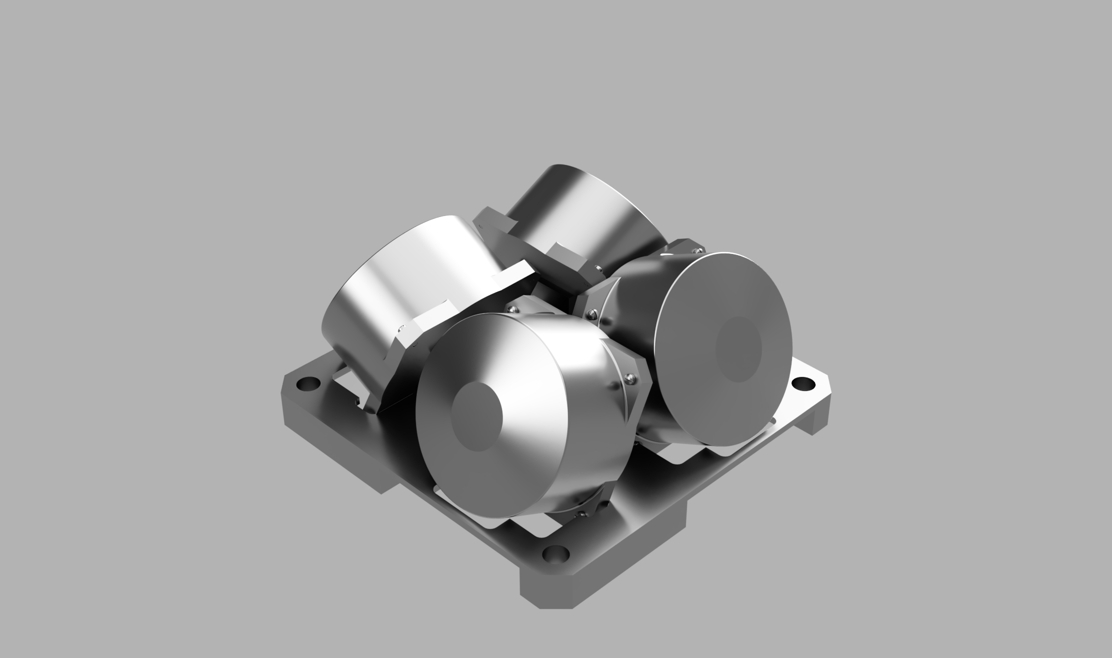
- Engineered instrument mounting interfaces for reaction wheels, magnetorquers, and a 9‑camera hyperspectral payload.
- Integrated reflectarray footprint and accommodation into the sail stowage and feed horn placement within the 1U volume.
- Prepared assembly and verification sequences (flat‑sat, vibration, shock) to de‑risk integration and test campaigns.
Tools & methods
Primary tools used on this project: Autodesk Fusion for CAD and Siemens Femap for finite‑element checks. Work followed iterative review cycles, flat‑sat integration, and generation of test procedures for qualification (vibration, shock, and functional deployment tests).